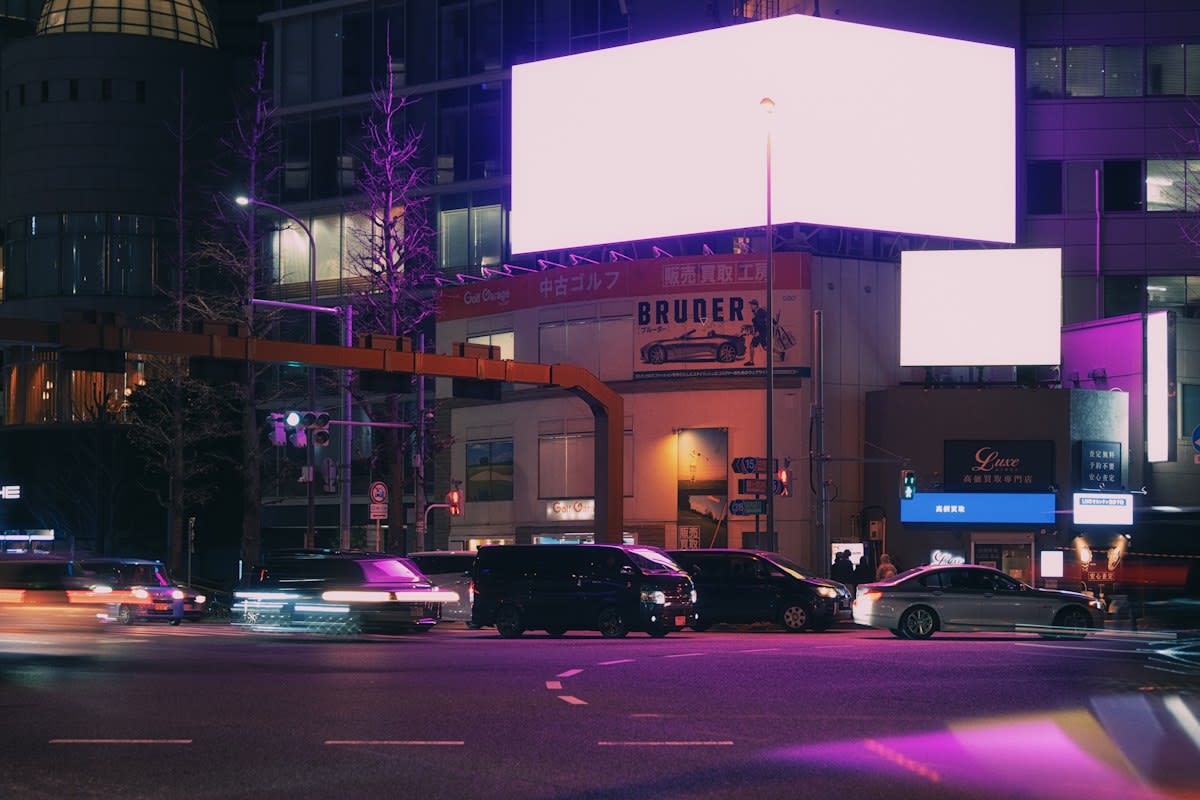
Most agencies treat urban LED screens as giant smartphones—flat rectangles designed for a front-facing audience. This is a fundamental misunderstanding of the medium. True anamorphic 3D is not about the screen; it is about the intersection of geometry, viewer positioning, and the physical architecture of the city. When we talk about ending the era of static advertising, we are not talking about moving images, but about images that physically break the plane of the building to create an immersive experience that captivates the viewer (Source: Facebook Project 001, 2024).
Prerequisites: The Technical Foundation
Before you touch a single keyframe, you need a hardware stack capable of handling massive data throughput without latency. Anamorphic illusions fail the moment a frame drops or a pixel bleeds. You are essentially creating a mathematical lie that the brain accepts as truth, and that lie requires absolute precision. You cannot achieve the necessary depth and clarity on legacy systems; the industry is shifting toward 8K visualization to maintain the illusion at scale (Source: postPerspective, 2017).
- High-density LED panels with seamless corner joins (L-shaped configurations are standard for the 3D effect).
- GPU clusters capable of 8K real-time rendering to prevent motion jitter (Source: postPerspective, 2017).
- Precise site survey data including the exact 'sweet spot' coordinates where the anamorphic projection resolves.
- Content pipeline supporting anamorphic lens simulation for pre-visualization (Source: kenerateai.com, 2026).
Understanding the Logic of Anamorphosis
To build a modern 3D LED experience, you must first understand that this is an ancient art. The core logic is identical to the anamorphic frescoes created by Emmanuel Maignan in 1637, where images were painted with extreme geometric distortion to appear as meaningless smears from most angles, only resolving into a recognizable scene when viewed from a single specific point (Source: spokenpast.com, 2026). In a modern urban setting, your 'single specific point' is the pedestrian crossing or the main traffic artery. If you design for the center of the screen rather than the eye-level of the viewer at that specific coordinate, the 3D effect collapses into a distorted mess.
From a practitioner's perspective, the most heated debates in the studio usually center on the 'Sweet Spot Conflict.' The creative team wants a wide viewing angle to capture more foot traffic, but the technical lead knows that widening the angle dilutes the depth perception. We often fight over whether to prioritize the 'hero' view—that perfect 45-degree angle where the object seems to float in mid-air—or to create a 'soft' anamorphic effect that works adequately from multiple positions. The reality is that you cannot have both; a perfect illusion requires a strict geometric constraint.
The Implementation Workflow
Executing these projects requires a phased approach that separates the macro-spatial logic from the micro-visual details. You cannot simply 'animate' a 3D object and slap it on a screen; you must build the environment first. Following a structured design process ensures that the final output aligns with the physical reality of the street corner (Source: zheniavasiliev.com, 2011).
- Phase 1: Macro-Spatial Analysis. Identify the primary viewer entry points and the physical boundaries of the LED installation. Map the 'sweet spot' where the geometric distortion will resolve into a 3D image.
- Phase 2: Singular Element Design. Focus on the shapes, colors, and features of the object breaking the plane. Determine how shadows will interact with the 3D parts of the drawing to create a sense of physical presence (Source: zheniavasiliev.com, 2011).
- Phase 3: Paper Structuring and Storyboarding. Before moving to digital formats, structure the movement on paper. Use anamorphic lens prompts during the storyboarding phase to simulate how the focal length (from 14mm to 135mm) affects the perceived depth (Source: kenerateai.com, 2026).
- Phase 4: Forced Perspective Rendering. Render the content using a virtual camera placed exactly at the viewer's sweet spot. The resulting 'distorted' image is what is actually played on the LED screen.
- Phase 5: On-Site Calibration. Adjust the render based on real-world ambient light and the actual physical bezel of the screen to ensure the object 'breaks' the edge cleanly.
"The progress of 8K visualization is critical for these installations because the human eye is incredibly sensitive to pixelation when it's trying to perceive depth in a forced-perspective environment."— Andrew Page, Product Manager at NVIDIA
Optimizing for Visual Impact
To make an object truly 'pop,' you must manipulate light and shadow to mimic the environment. This is the 'drawing with light' technique. By creating artificial shadows that appear to fall on the 'internal' walls of the LED box, you convince the viewer's brain that there is a physical volume behind the screen surface (Source: zheniavasiliev.com, 2011). If the lighting in your render doesn't match the general luminosity of the city street, the illusion feels like a sticker rather than a window.
Furthermore, the choice of lens simulation during the pre-production phase is non-negotiable. Using a spherical prime lens for a 3D LED project is a mistake. You need the characteristics of anamorphic or fisheye lenses to properly map the distortion required for the viewer's perspective (Source: kenerateai.com, 2026). This allows the content to 'break out' into the space, creating a mix of digital drawing and 3D object quality that captivates the audience (Source: zheniavasiliev.com, 2011).
Fact-Check & Accuracy Note
The claims regarding the necessity of 8K for high-fidelity visualization are sourced from NVIDIA's professional visualization insights (2017). The geometric principles of anamorphosis are verified by historical records of 17th-century Italian frescoes (Source: spokenpast.com, 2026). The design process phases are based on practitioner notes from Zhenia Vasiliev (2011).
Common Pitfalls to Avoid
The most common failure in 3D LED projects is the 'Center-Screen Trap.' Designers often place the action in the middle of the display, forgetting that the illusion only works if the object interacts with the edges of the screen. If an object stays in the center, it's just a video in a box. For the 3D effect to trigger, the object must appear to cross the physical boundary of the LED panel, creating the sensation that it is entering the viewer's physical space.
- Ignoring the 'Sweet Spot': Designing for a general audience instead of a specific coordinate.
- Lighting Mismatch: Using studio lighting in the render that contradicts the urban environment.
- Over-Animation: Moving the object too quickly, which breaks the brain's ability to process the forced perspective.
- Hardware Bottlenecks: Attempting 3D depth on low-resolution panels, resulting in 'stair-stepping' on the edges of the 3D objects.